ARCHES Mount Etna DataSet
Online: 17 May 2023 – Latest Update: 31 October 2023

Context
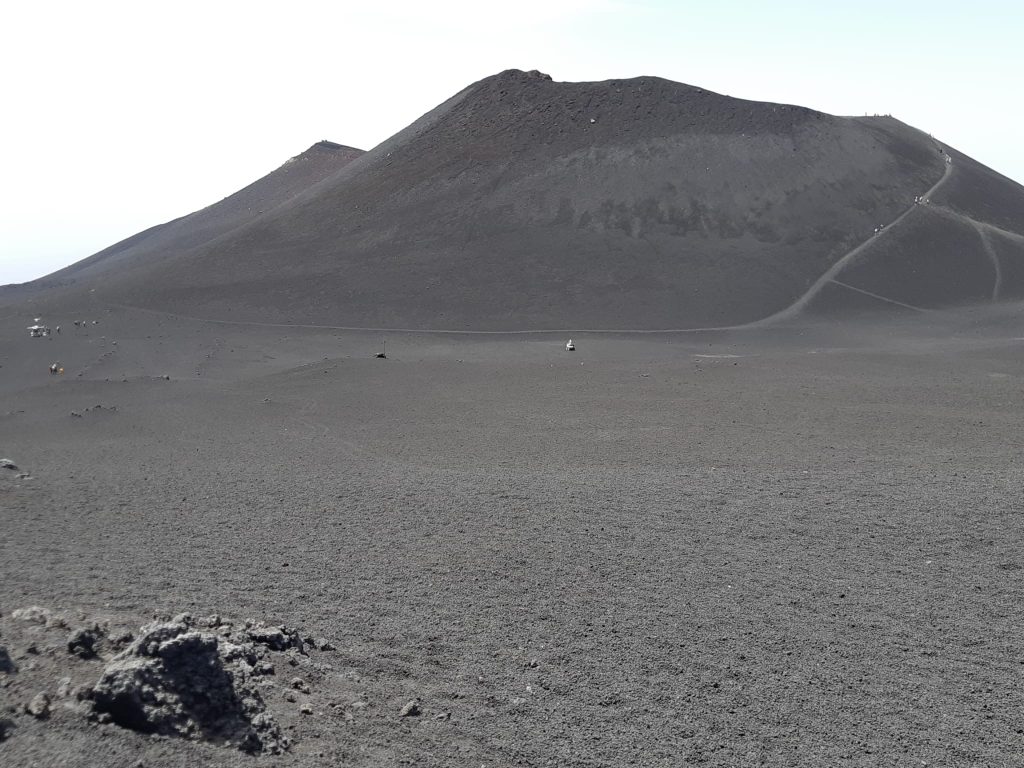
This dataset was acquired during a test campaign performed on the slopes of Mount Etna in the summer of 2022 by ESA’s Human Robotic Interaction lab (HRI). The test campaign was organised by the German Aerospace Center (DLR) as part of the Autonomous Robotic Networks to Help Modern Societies project (ARCHES) in collaboration with the European Space Operations Center (ESOC). Following the original test campaign, the HRI’s Interact rover was used to perform a series of 9 traverses and 2 rock picking experiments, during which the data from the onboard sensors was recorded and converted into a convenient timestamped format in order to produce a multi-disciplinary robotic dataset from a lunar analogue environment. The intention of this dataset is to offer the scientific community new data specifically targeted to the emerging field of lunar Space robotics. It is indeed to date, the only robotic dataset to have been collected on Mount Etna, which serves as a great analogue for the gray, rocky, and otherwise relatively devoid surface of the Moon. More specifically, as the dataset contains raw sensor data, processed data and ground truth models from a large fleet of sensors, it is particularly suitable for testing algorithms for localization, visual and laser odometry, object detection, slope detection and 3D mapping. It can also be interesting in the field of human-robot teleoperation, in order to research user comfort when facing live lunar telemetry and video feed during Space exploration operations. However, it is important to note that this dataset was not initially planned as part of the HRI’s activities during the ARCHES campaign. As a result, it lacks some of the sensor calibration precision found in similar publications. This limitation has been remedied as best as possible by providing an extensive amount of complimentary information on the rover and sensors used for acquiring the dataset, and by performing calibrations after the data acquisition with complete transparency for the reader.
Rover Platform, Sensors and Actuators
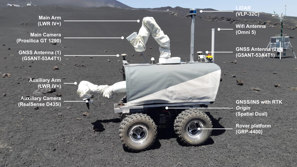
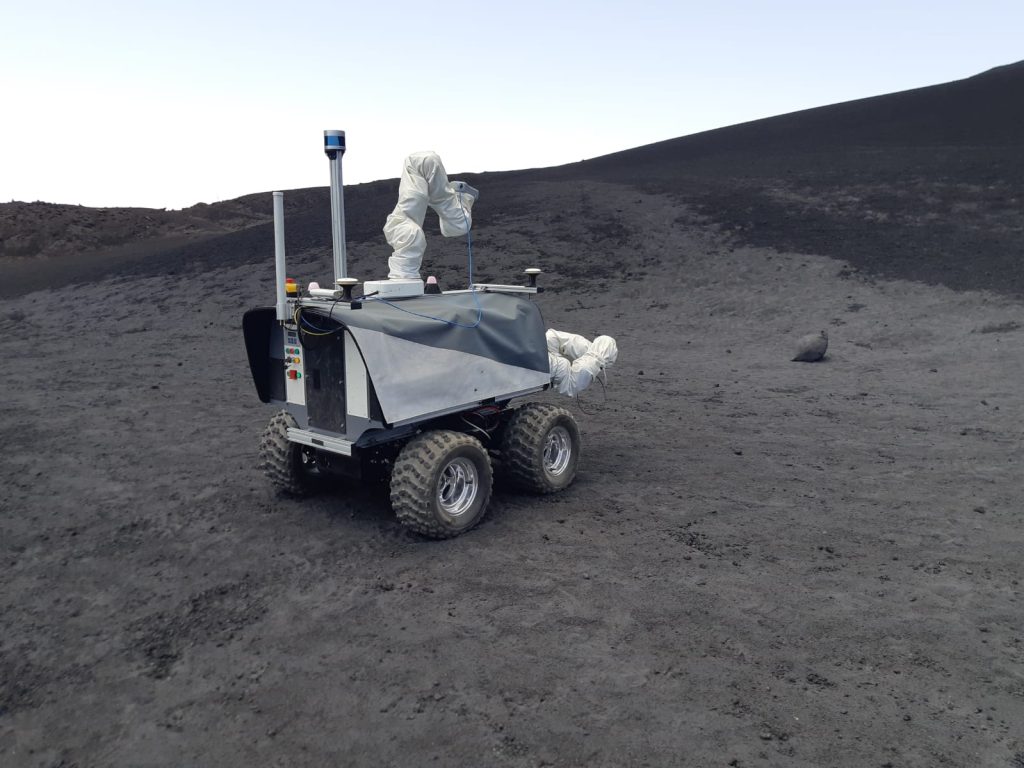
The Interact rover was used to collect this dataset thanks to its numerous onboard sensors and actuators. Its sturdiness, gamepad based control and 4-wheel drive makes it a suitable robotic platform for data collection in all sorts of hazardous and rugged environments such as the slopes of Mount Etna.
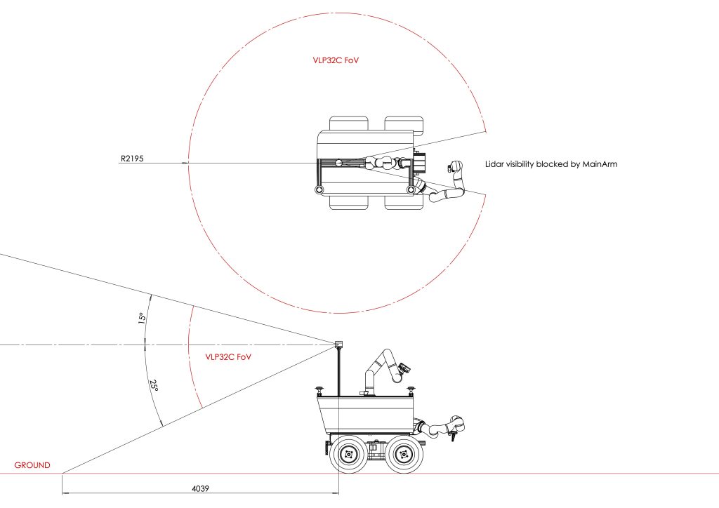
Interact’s rover platform is a robust 4-wheel steer and drive GRP-4400 from Ambot with encoder readings for both the steer and drive motors. For global localization and orientation, Interact is fitted with a inertial navigation system (GNSS/INS & AHRS) Spatial Dual from Advanced Navigation, combining the power of a Real-Time Kinematic positioning (RTK) compatible GNSS receiver, an Inertial Measurement Unit (IMU) and pressure sensor for high precision pose measuring. For higher heading precision and better signal reception, two GNSS antennas G5ANT-53A4T1 from Antcom are placed at both extremities of the rover. A Velodyne VLP-32C LiDAR is mounted on top of Interact in order to cover a large circular field-of-view around the rover. Centered on Interact’s back is a LWR IV+ 7 degree-of-freedom (DOF) robotic arm from Kuka which is equipped with a Prosilica GT 1290 high performance machine vision camera mounted with a Ricoh FL-CC0418DX-VG 2/3” lens referred to as Main Camera or simply MainCam. Finally, a second LWR IV+ arm is mounted in front of Interact and is equipped with a Realsense D435i depth camera from Intel referred to as Auxiliary Camera or simply AuxCam.
| Device (Manufacturer) | Name | Type | Notable Specifications |
| GRP-4400 (Ambot) | Platform | Rover platform | – 4 wheel steer and drive (independent) – 250 kg payload capacity – 20 cm clearance – Steer and drive encoders |
| LWR IV+ (Kuka) | AuxArm / MainArm | 7-DOF robotic arm | – +- 0.15 mm pose repeatability – 820 mm maximum reach – 14 kg payload capacity |
| Prosilica GT 1290 Ricoh FL-CC0418 DX-VG 2/3” (Allied Vision) | MainCam | Camera (color) | – 15 fps – 1920 x 1080 (HD) res. – Auto exposure and gain – 96.4° x 54.2° FOV (H x v) |
| Spatial Dual (Advanced Navigation) | Gnss | GNSS/INS & AHRS (RTK) | – 8 mm horizontal position acc. – 15 mm vertical position acc. – 7 mm/s velocity acc. – 0.03° roll and pitch acc. – 0.06° yaw acc. |
| Realsense D435i (Intel) | AuxCam | Depth Camera (color) | – 30 fps – 1280 x 720 res. – 69° x 42° FOV (H x v) |
| VLP-32C (Velodyne) | Lidar | LiDAR (scanning) | – 32 laser channels – 200 m range – 3 cm range acc. – 360° x 40° FOV (H x v) – 300 rpm – Capture mode: strongest |
Sensor and Actuator Coordinate Frames and Relative Poses
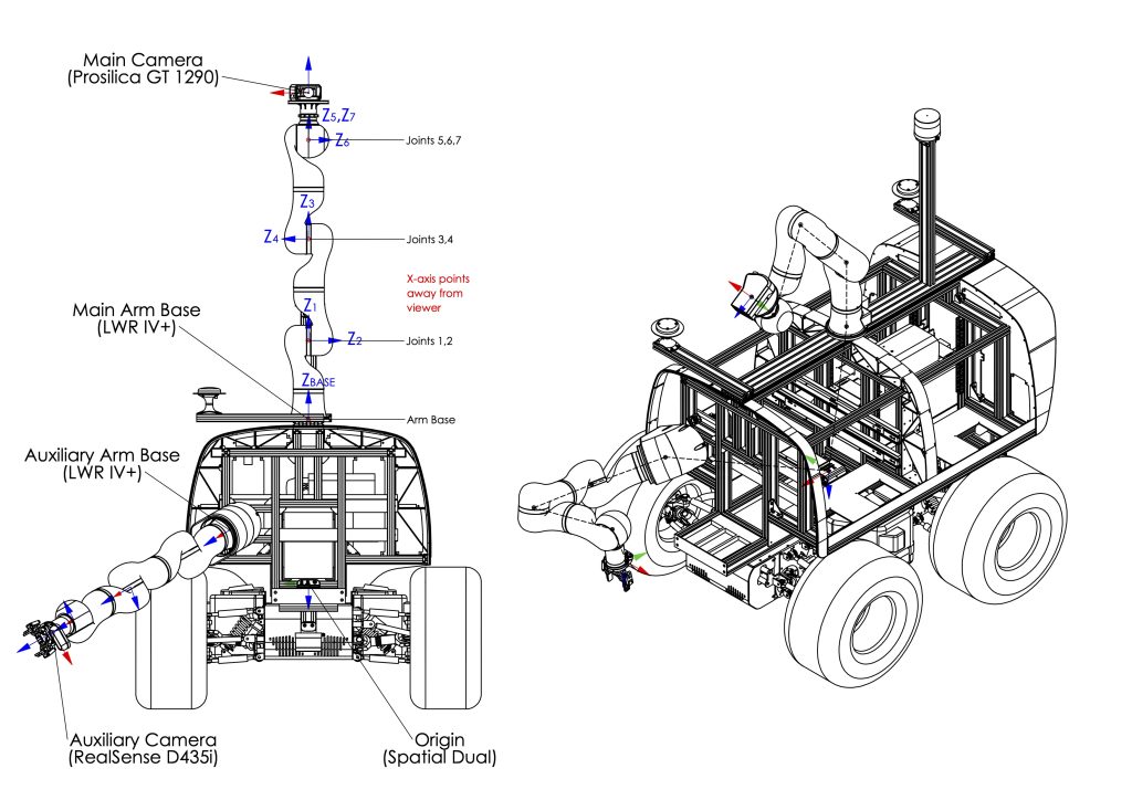
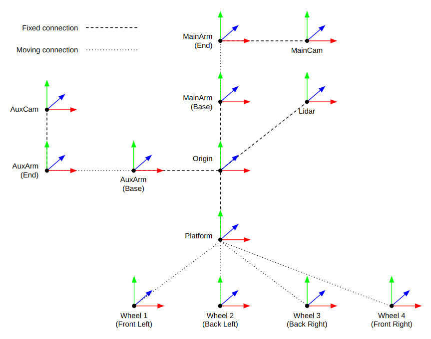
All the onboard sensors have predefined coordinate frames which can be used to transform data to a global coordinate system or compare points-of-interest between sensors. The Spatial Dual’s origin and coordinate frame is defined as being the origin of Interact. The Lidar‘s coordinate system is fixed, while those of the cameras and the wheels depend on the robotic arm joint angles and the steer angles respectively. While the MainArm can act as a pan-and-tilt unit for the MainCam, it was kept in a stationary position during the dataset acquisition. The AuxArm on the other hand has a gripper mounted at its end-effector for rock sampling and is only stationary during traverses (c.f. traverse 0 through 8), but not during rock picking experiments (c.f. rock picking 0 and 1).
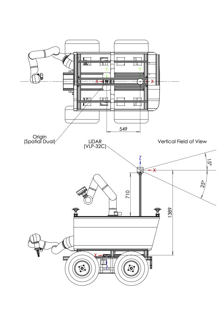
The North-East-Down (NED) coordinate system origin of the “world”, in which Interact is globally localized, is located at 37.72351° (latitude), 15.00668° (longitude) and 2639.838 m (altitude) in WGS84 standard. This location corresponds to the position of the ARCHES campaign lander and is located at the bottom of the test site (see Figure 16). The CAD drawings below provide a detailed view of all the reference frames of the different sensors onboard Interact and where they are located with respect to the Origin. PDF versions of the drawings can be downloaded here.


Below is a table that summarizes the fixed relative transformations between Interact’s onboard devices. These values are derived from the CAD model of the robot and are subject to slight offsets due to mounting inaccuracies. These offsets can be as severe as 5mm in positioning accuracy and 2° in orientation accuracy. Vibrations caused by the uneven terrain can also considerably affect the position of all the sensors, notably the Lidar, and can cause offsets that are unaccounted for. No extrinsic calibration of the sensors was performed before the dataset acquisition. A YAML file containing the fixed transformation matrices can be downloaded here. For the reader’s convenience, all translation values (xBA, yBA, zBA) are given in mm, while all rotation values (ψx, θy, φz) are given in degrees. The rotation values correspond to the three Euler angles given in XYZ extrinsic convention, also known as Tait-Bryan angles (i.e. first rotation about z, then y and then x with respect to the fixed original coordinate system).
| From frame A | To frame B | xBA | yBA | zBA | ψx | θy | φz |
| Lidar | Origin | -549 | 0 | -1389 | 180 | 0 | 180 |
| MainArm Base | Origin | -100 | 0 | -647 | 0 | 180 | 0 |
| MainArm End | MainArm Base | Not | fixed | ||||
| MainCam | MainArm End | 28 | 0 | 186 | 0 | -90 | 90 |
| AuxArm Base | Origin | 598 | 310 | -210 | -60 | 50 | 180 |
| AuxArm End | AuxArm Base | Not | fixed | ||||
| AuxCam | AuxArm End | -57 | 0 | 218 | 0 | 18 | 90 |
| Platform | Origin | 0 | 0 | 81 | 180 | 0 | 0 |
| Wheel 1-4 | Platform | Not | fixed |
The AuxArm Base angular transformation values are equivalent to (40°, 120°, 90°) sequential rotations in the yzy intrinsic Euler convention, also known as proper Euler angles (see Figure 4 to better understand how these values are determined).
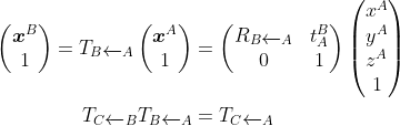
The values in the table above are meant to be interpreted as the transformation that needs to be applied to transform a point xA from the coordinate frame A to the coordinate frame B (i.e.xB). In other words, they correspond to the translation and rotation of the coordinate frame B relative to the coordinate frame A. These values can directly be used to create a homogeneous transformation matrix to convert between frames as follows:
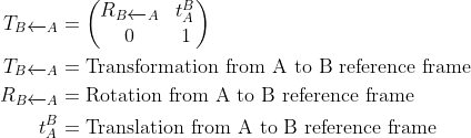
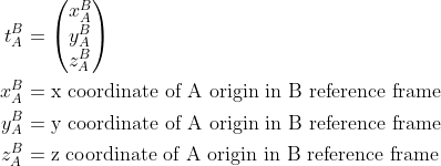
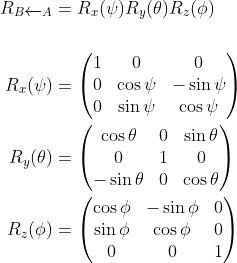
Where the following relationships hold:
Robotic arm pose computation
In order to use the images provided in the dataset as a source of odometry, for mapping, for object detection or for depth estimation (provided that there is overlap between both cameras), the pose of the cameras with respect to a common coordinate system need to be precisely known (extrinsics) as well as the camera parameters (intrinsics). Given that both cameras are mounted at the end of robotic arms that act as a pan-and-tilt unit, it is possible to compute their pose relative to the Interact’s origin. The robotic arms’ End-effectors’ coordinate frames relative to their Bases’ coordinate frames are dependent on the arms’ joint angles and link lengths. The link lengths are provided by Kuka and the joint angles are provided by integrated sensors. Therefore using the Denavit-Hartenberg modified DH parameters it is possible to determine the homogeneous transformation matrix between the arm’s End-effector and the Base. Below is a table that summarizes the LWR IV+ modified DH parameters (α, d, θ, r), where α is the angle about the common normal, d is the offset (along previous z) to the common normal and r is the length of the common normal. The angle θ about the previous z of each joint is given by the arm’s joint angle sensors.
| Link # | α (°) | d (m) | r (m) |
| 1 | 0 | 0 | 0.31 |
| 2 | 90 | 0 | 0 |
| 3 | -90 | 0 | 0.4 |
| 4 | -90 | 0 | 0 |
| 5 | 90 | 0 | 0.39 |
| 6 | 90 | 0 | 0 |
| 7 | -90 | 0 | 0 |
Steering angle, drive angle and wheel pose computation
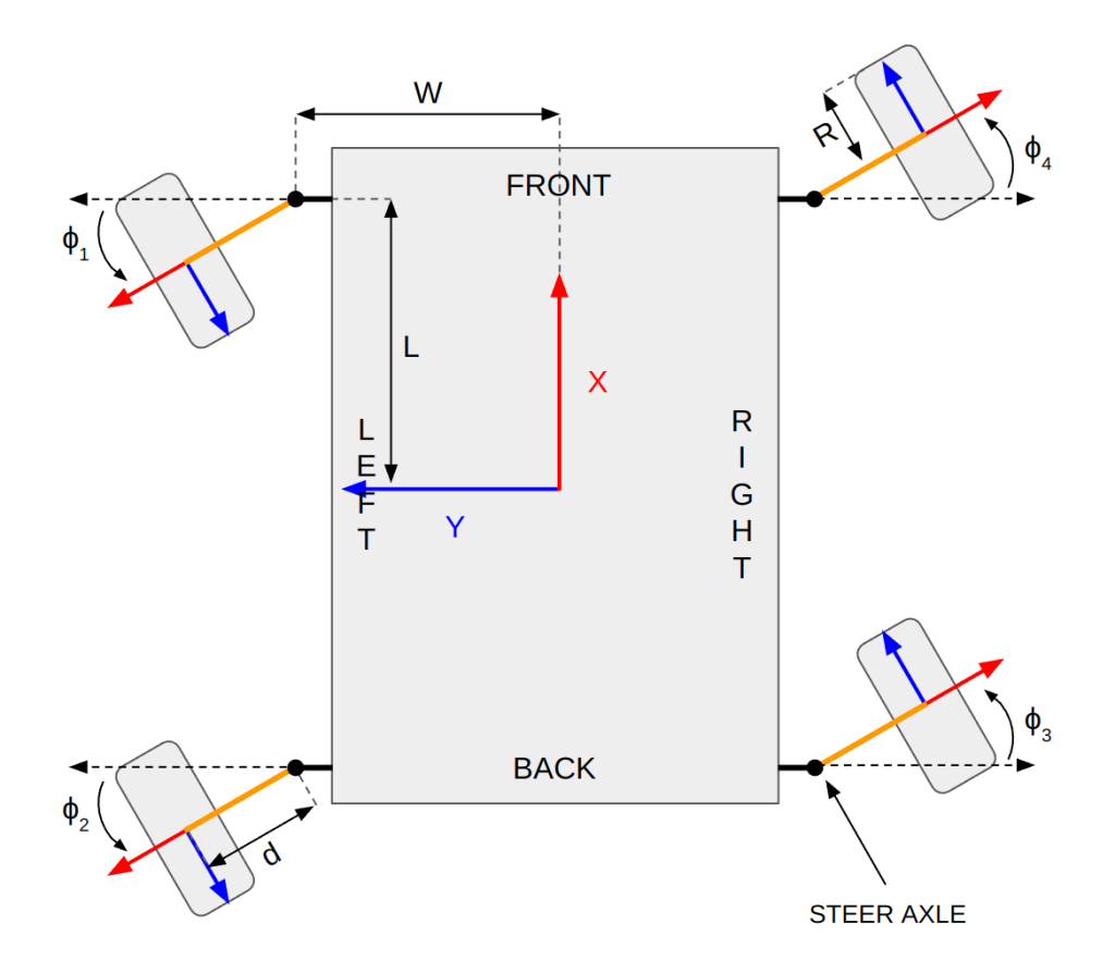
The pose (position and orientation) of the GRP-4400 rover Platform wheels depend on three variable parameters, the drive angle (ψ), the steering angle (φ) and the suspension height (h), as well as the Platform‘s dimensional parameters. The drive angle and the steering angle can be deduced from the Platform‘s motor encoders, but the suspension height is not measured and can therefore not be taken into account. The dimensional parameters, intrinsic to each wheel, are dependent on the Platform‘s half length (L=402mm), half width (W=396mm), wheel height at rest (H=135mm) and steer axle (swivel) length (d=143mm) (see Figure 5). The drive angle (in degrees) can easily be computed as follows:
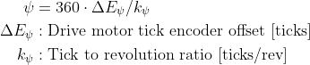
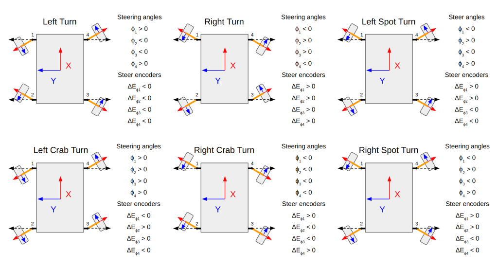
In the above equation, the tick offset can be measured via the drive motor encoders and the tick to revolution ratio of the drive motor is 30000 ticks/rev. The drive motor encoder values increase when the rover is moving forward and decrease when it is moving backwards. The steering angles are computed based on the convention depicted in Figure 9. This convention implies that the rover steering angles are all positive when the rover is performing a “Left Crab Turn”. All the possible Platform manoeuvres are shown in Figure 10. During the AMEDS data gathering only “Left Turns” and “Right Turns” were commanded. However, in some occasions, due to loose terrain below the rover producing considerable slip, the actual manoeuvres peformed by the rover are sometimes more similar to “Crab Turns” or “Spot Turns”.
Due to the Platform‘s transmission design, the suspension height influences the steering angle. Since the height cannot be measured, the suspension needs to be considered fixed at its rest position, which in turn can produce inaccuracies in the steering angle estimation. However, the following equation, deduced empirically by the HRI lab via a CAD analysis, estimates relatively accurately the steering angle (in degrees):
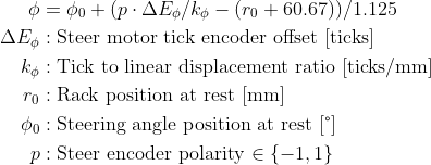
In the above equation, the tick offset can be measured via the steer motor encoder, the tick to linear displacement ratio of the steer motor (linear actuator) is 806.3 ticks/mm, the rack position at rest is 40.58 mm, and the steering angle position at rest is 90°. For both front wheels (wheel 1 and 4), a positive encoder value corresponds to a negative steering angle. Therefore a multiplication factor, or polarity, equal to -1 (i.e. p = -1) needs to be introduced for the front wheels in order to respect the convention stated above. Once the drive angles and steering angles are known, it is easy to use a little trigonometry to determine the position of each wheel with respect to the Platform‘s coordinate system as follows:
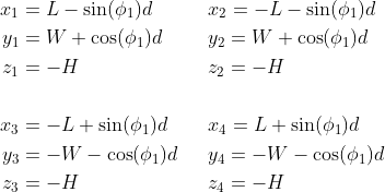
The orientation of each wheel can be termined using the sequential rotations (α, β, γ) in zxz intrinsic Euler convention (i.e. first rotation about z, then x and then y with respect to the rotating coordinate system) as defined in the table below:
| Wheel # | α (°) | β (°) | γ (°) |
| 1 | 0 | ψ1 | φ1+90 |
| 2 | 0 | ψ2 | φ2+90 |
| 3 | 0 | -ψ3 | φ3-90 |
| 4 | 0 | -ψ4 | φ4-90 |
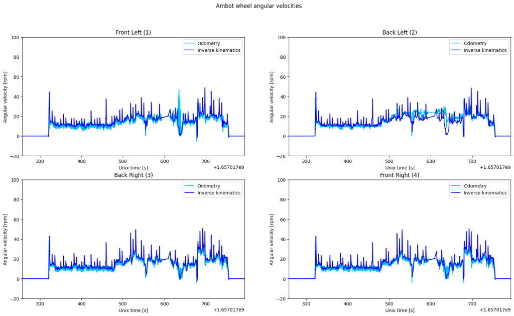
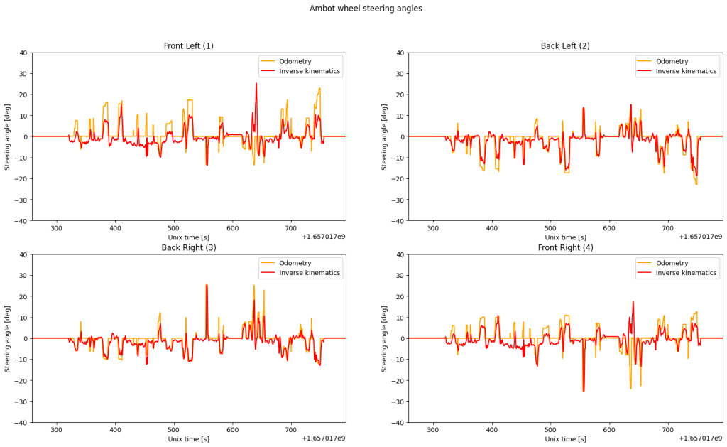
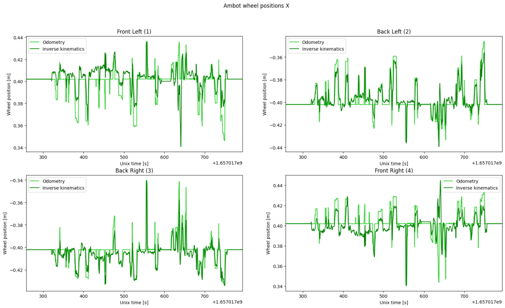
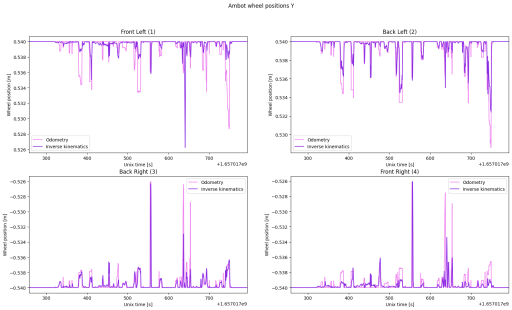
The quality of this odometry based approach has been verified by comparison to an inverse velocity kinematics approach detailed in Vector Algebra Formulation of Mobile Robot Velocity Measurements by Alonzo Kelly and Neal Seegmiller, which uses the Platform twist estimate as the velocity source. In this analysis, vertical body velocity is considered zero and the suspension height is considered fixed. The outcome of this analysis can visually be seen in an example from traverse 1 in the figures below. A inverse kinematics approach can typically be useful to determine slippage, while odometry can be used in fusion algorithms for localization.
Camera Intrinsic Calibration
Post dataset collection, both cameras’ intrinsic calibration parameters were estimated using the open-cv methodology available open-source in both python and c++. The results of these calibrations are available for download here and are summarised in the table below:
| Intrinsic parameters | fx | fy | cx | cy | γ |
| AuxCam | 908.087 | 910.723 | 656.119 | 356.394 | 0 |
| MainCam | 885.015 | 887.440 | 955.893 | 533.638 | 0 |
| Distortion parameters | k1 | k2 | p1 | p2 | k3 |
| AuxCam | 0.1431 | -0.4744 | 0.00068 | 0.00123 | 0.4215 |
| MainCam | -0.2418 | 0.0974 | 0.00048 | 0.00019 | -0.0226 |
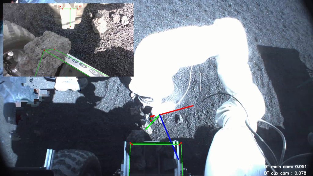
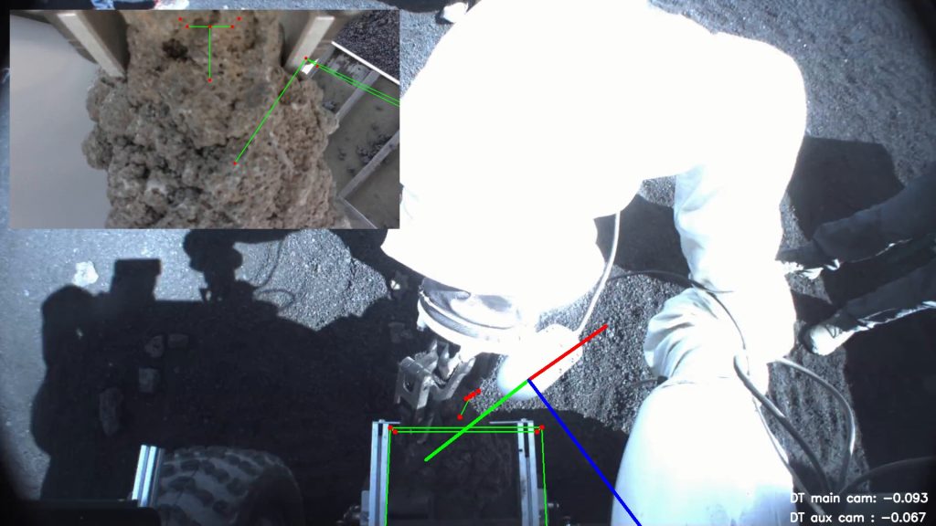
The quality of both the intrinsic and extrinsic calibration has been visually evaluated by projecting “known” parts of Interact (e.g. rock container, gripper and AuxCam coordinate frame) onto the MainCam and AuxCam images from the two rock-picking experiments (see Figure 15). Via this simple analysis, it is noticeable that cm level offsets are present in the projections at roughly 1m and 50cm distance from the camera in the MainCam and AuxCam images respectively. These offsets are likely due to a summation of errors in the camera extrinsics, camera intrinsics, rover construction and the position of the camera origin.
Overview of Traverses
The traverses dataset consists of 9 short traverses, whose starting points and end points are connected, and thus can be combined to form a single large traverse. The first 7 traverses are realistic when compared to a robot rovering within a lunar environment. Whereas the last 2 traverses were captured when returning the rover to the control centre and do not hold as much realism with respect to the surroundings (i.e. cars and humans are visible) and rover behaviour (i.e. rover is driving backwards). Below is an aerial view of the traverses along with a heightmap of the traversed area and the locations of the lander and control centre. A summary of the main characteristics of each traverse is also displayed in a table below.
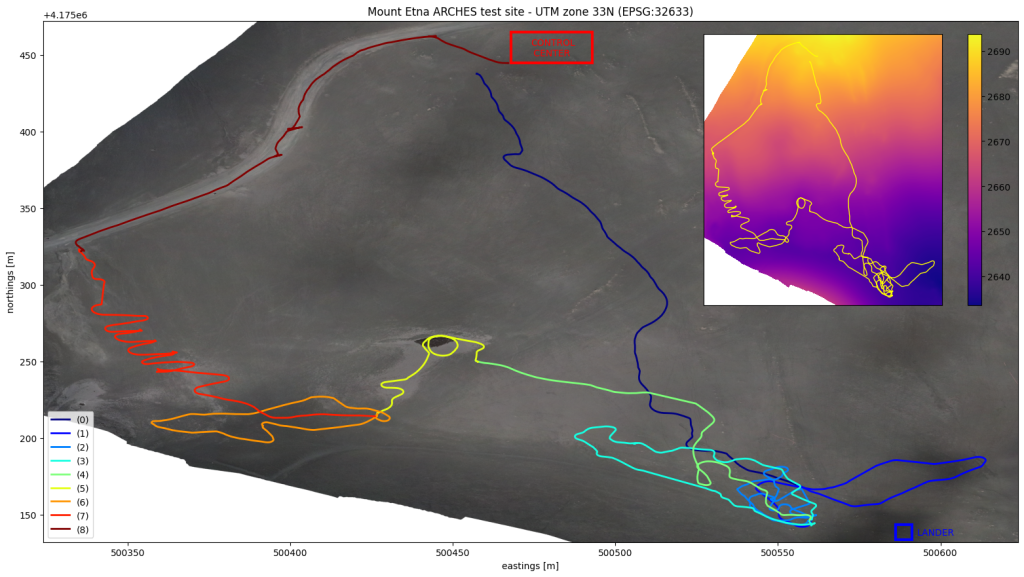
| # | Length (m) | Max height difference (m) | Duration (mm:ss) | Mean velocity (m/s) | RTK coverage |
| 0 | 329.8 | 46.6 | 25:02 | 0.22 | No |
| 1 | 195.6 | 4.7 | 08:55 | 0.36 | No |
| 2 | 202.8 | 1.7 | 08:46 | 0.41 | Yes |
| 3 | 239.1 | 4.8 | 14:44 | 0.30 | Yes |
| 4 | 210.9 | 9.6 | 07:26 | 0.50 | Yes |
| 5 | 134.1 | 6.5 | 09:31 | 0.37 | Yes |
| 6 | 191.7 | 2.1 | 09:39 | 0.39 | No |
| 7 | 304.2 | 22.2 | 08:26 | 0.67 | No |
| 8 | 246.6 | 22.4 | 06:40 | 0.81 | No |
| Tot | 2054.8 | – | 99:09 | – | – |
The data was recorded and compressed into sqlite databases with XCDR encoding directly onto the rover’s main computer storage, which during roll-over sometimes produces small time gaps of unrecorded data. Additionally, due to uncontrollable reasons, not all the recordings were captured with an RTK fix, therefore some of the recordings are captured with a lower accuracy Differential or SBAS fix.
Overview Rock Picking Experiments
The rock picking dataset is comprised of 2 stationary rock picking experiments, during which the AuxArm and it’s gripper end-effector are used to pick-up a rock in view of the onboard cameras and store it in a small container in front of the rover. Both experiments take place in front of the control centre. The rock picking experiment 0 and 1 last 2 minutes 21 seconds and 1 minute 45 seconds respectively.

Dataset Content and Links
The dataset is comprised of both raw sensor data (straight from the sensor, unaltered by mathematical calculations) and processed data (based on raw data but transformed either onboard in near real-time or during post-processing with python scripts). All the data is timestamped by the RTI Connext DDS middleware, which is based on the onboard computers’ clocks. All computers running on Interact were time synced with a common Network Time Protocol (NTP) server. Below is a list of the data provided in this dataset as well as some insightful information concerning the format and the content of the files as well as the acquisition frequency.
Raw sensor data
AuxArm (LWR IV+)
- AuxArmJointAngles.csv – 1 Hz
- Timestamp [unix seconds]
- Joint 1-7 angles [rad]
AuxCam (Realsense D435i)
See user manual for more information on the sensor
- AuxCam_unixseconds.jpg – 30 Hz
- 1280×720 pixel color image (unrectified)
- AuxCamVideoFeed.mp4 – 30 fps
- Reconstructed color video feed (unrectified)
Gnss (Spatial Dual)
See user manual for more information on the sensor
- GnssBodyAcceleration.csv – 100 Hz
- Timestamp [unix seconds]
- (x, y, z) acceleration [m/s/s]*
- GnssBodyAngularVelocity.csv – 100 Hz
- Timestamp [unix seconds]
- (x, y, z) angular velocity [rad/s]*
- GnssBodyVelocity.csv – 100 Hz
- Timestamp [unix seconds]
- (x, y, z) velocity [m/s]*
- (x, y, z) std velocity [m/s]
*Velocity/acceleration of body frame in body coordinates with respect to the fixed ground
- GnssImu.csv – 100 Hz
- Timestamp [unix seconds]
- (x, y, z) accelerometer [m/s/s]
- (x, y, z) gyroscope [°/s]
- (x, y, z) magnetometer [G]
- Imu temperature [°C]
- Outside pressure [Pa]
- Outside temperature [°C]
- GnssNedVelocity.csv – 100 Hz
- Timestamp [unix seconds]
- (x, y, z) NED velocity [m/s]
- (x, y, z) std NED velocity [m/s]
- GnssPose.csv – 100 Hz
- Timestamp [unix seconds]
- Device timestamp [unix seconds]
- (lat, lon, alt) geodetic position [rad, rad, m]
- (x, y, z) NED position [m]
- (x, y, z) std NED position [m]
- (roll-x, pitch-y, yaw-z) NED attitude [rad]
- (roll-x, pitch-y, yaw-z) std NED attitude [rad]
- gnss fix type [0-7]
Lidar (VLP-32C)
See user manual for more information on the sensor
- LidarPointcloud_unixseconds.pcd – 5 Hz
- Reconstructed pointcloud from one full revolution with point intensities indicating surface reflectance (0-255)
MainArm (LWR IV+)
- MainArmJointAngles.csv – 1 Hz
- Timestamp [unix seconds]
- Joint 1-7 angles [rad]
MainCam (Prosilica GT 1920)
See user manual for more information on the sensor
- MainCam_unixseconds.jpg – 15 Hz
- 1920×1080 pixel color image (unrectified)
- MainCamVideoFeed.mp4 – 15 fps
- Reconstructed color video feed (unrectified)
Platform (GRP-4400)
- PlatformMotorEncoders.csv – 50 Hz
- Timestamp [unix seconds]
- Drive motor 1-4* velocity [m/s]
- Drive motor 1-4 cmd velocity [m/s]
- Drive motor 1-4 position [ticks]
- Steer motor 1-4 position [ticks]
*The numbering of the drive and steer motors are as follows:
1 – Front left wheel
2 – Back left wheel
3 – Back right wheel
4 – Front right wheel
- Platform2DVelocity.csv – 50 Hz
- Timestamp [unix seconds]
- (x, y) velocity [m/s]*
- (z) angular velocity [rad/s]*
- (x, y) std velocity [m/s]
- (z) std angular velocity [rad/s]
*Velocity of body frame in body coordinates with respect to the fixed ground
Processed data
AuxCam (Realsense D435i)
- AuxCamPoseEstimate.csv – 1 Hz
- Timestamp [unix seconds]
- (x, y, z) position [m]
- (roll-x, pitch-y, yaw-z) attitude [rad]
MainCam (Prosilica GT 1920)
- MainCamPoseEstimate.csv – 1 Hz
- Timestamp [unix seconds]
- (x, y, z) position [m]
- (roll-x, pitch-y, yaw-z) attitude [rad]
- MainCamAuxCamProjected_unixseconds.jpg – 15 Hz
- MainCam and AuxCam images with rock container, gripper and AuxCam coordinate frame projections
Platform (GRP-4400)
- Platform2DPoseEstimate.csv – 100 Hz
- Timestamp [unix seconds]
- (x, y) NWU position [m]
- (yaw-z) NWU attitude [rad]
- (x, y) std NWU position [m]
- (yaw-z) std NWU attitude [rad]
- Platform2DTwistEstimate.csv – 100 Hz
- Timestamp [unix seconds]
- (x, y) velocity [m/s]*
- (z) angular velocity [rad/s]*
- (x, y) std velocity [m/s]
- (z) std angular velocity [rad/s]
*Velocity of body frame in body coordinates with respect to the fixed ground
- PlatformWheelPoseEstimate.csv – 100 Hz
- Timestamp [unix seconds]
- Wheel 1-4 (x, y, z) position [m]
- Wheel 1-4 (roll-x, pitch-y, yaw-z) attitude [rad]
- Wheel 1-4 drive angle [rad]
- Wheel 1-4 steering angle [rad]
Depending on the source of positional, angular, velocity and acceleration measurements the coordinate system convention can vary between body frame, NED (North-East-Down) and NWU (North-West-Up). When not explicitly mentioned, the measurements are given in body frame. All the data files from one traverse or experiment are bundled together into a single folder and compressed into a zip format. The data from each traverse and rock picking experiment can be downloaded via the links below.
Traverse dataset downoad links


Rock picking dataset download links
Rock picking 0 (2.1 GB)
Rock picking 1 (2.2 GB)
Helpful Tools and Information
Useful python scripts
Below is a list of python scripts that were written to post-process some of the data and create the images found within the dataset files and this website. These scripts are for reference only as they require the licensed connext-dds library to decode the sqlite data files containing the recorded data. However, a simple editing of the script can make them process the converted csv files instead. If the user wishes to make use of the original connext dds recordings in sqlite format, please contact the HRI lab at the following address: thomas.krueger@esa.int. Most of the scripts inherit from the loaddatasetparameters.py script and require the IDL files to decode the recorded data, which can be downloaded here.
Generate Images – generateimages.py
This script superimposes the GnssPose position data onto TIF images from the ARCHES test site in order to create an overview satellite image of all the traverses combined (see Figure 16). It also computes the statistics of all the trajectories.
The TIF images used in this script can be downloaded below:
ARCHES test site orthophoto
ARCHES test site slopes
ARCHES test site digital elevation model
Project Camera Frame –projectcameraframe.py
This script projects “known” coordinates of parts of Interact, such as the rock container edges, gripper features and the AuxCam coordinate frame, onto the MainCam and AuxCam images to help the user evaluate visually the quality of the cameras’ intrinsic and extrinsic calibrations.
Sqlite Data to Camera Pose – sqlite2camerapose.py
Using the DH parameters of the robotic arms (MainArm and AuxArm), the arms’ respective joint angles and the relative poses of the arms base and cameras (MainCam and AuxCam), this script computes the cameras’ poses with respect to the Interact origin by multiplying homogeneous transformation matrices.
Sqlite Data to Images –sqlite2images.py
All camera data recorded in this dataset is compressed using the H264 video compression standard. This implies that the sqlite databases, containing the video topics, are not made-up of standard images, but rather encoded H264 frames. Using the script provided above, it is possible to decode, or rather reconstruct, the images with their respective timestamps. The script initializes and runs a gstreamer pipeline in order to read and convert into images the recorded H264 frames provided by the sqlite database. Once an image has been reconstructed from a frame, it is saved as an image file (jpeg or png) with the source timestamp in the filename.
Sqlite Data to Pointcloud – sqlite2pointcloud.py
The Lidar data recorded in this dataset contains the individual timestamped 3D points returned by the sensor with their respective reflectances. This script combines the 3D points from one full revolution of the sensor into a single (and more handy) pcd pointcloud format.
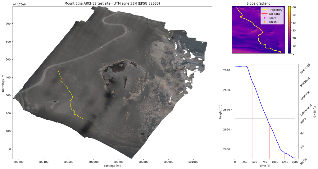
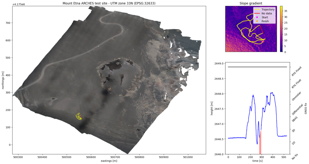
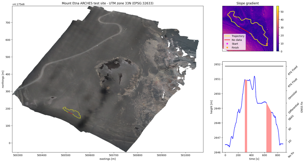
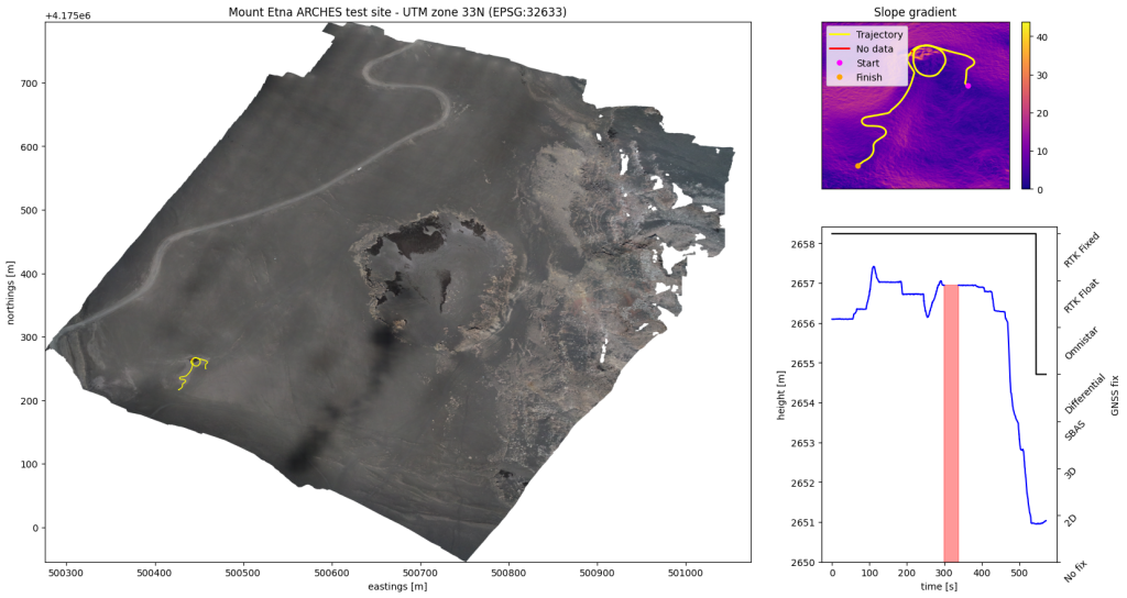
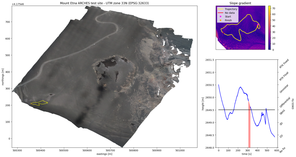
Sqlite Data to Satellite Image Trajectory – sqlite2satimagetrajectory.py
This script superimposes the GnssPose position data from an individual traverse onto TIF images from the ARCHES test site in order to create an overview satellite image with slope information. It also plots the rover’s altitude and RTK coverage as a function of time, and indicates when and where data losses occured.
Sqlite Data to Wheel Velocity and Pose – sqlite2wheelvelocity.py
Using both the inverse kinematics approach from the Vector Algebra Forumulation of Mobile Robot Velocity Measurements by Alonzo Kelly and Neal Seegmiller and the odometry approach, this script estimates the platform’s wheel velocities and poses with respect to Interact’s origin. As a by product of the pose estimation, the script also computes the steering and drive angles for each wheel, and generates comparison plots of both approaches.
Algorithms used for processing data in real-time
Platform 2D Pose and 2D Twist Estimate
In order to estimate Interact’s 2D pose and 2D twist to a higher precision, a custom sensor fusion algorithm was used, which combines an Augmented Unscented Kalman Filter (Augmented UKF) with a Constant Turn-Rate Velocity (CTRV) model for predicting the motion of the vehicle. The UKF implementation follows closely the algorithm from Probabilistic Robotics by Sebastian Thrun, Dieter Fox and Wolfram Burgard (Section 3.4.2 – Table 3.4 (Standard UKF) and Section 7.7 – Table 7.4 (Augmented UKF)), as well as the paper The Unscented Kalman Filter for Nonlinear Estimation by Eric A. Wan and Rudolph van der Merwe. The Augmented form includes the process noise as a state to be estimated but does not include the measurement noise. The algorithm fuses data from the Platform 2D velocity and the Gnss NED position and attitude.
Citation
The information and data provided on this website is accompanied by a publication. If you use the data provided by this website in your work, please make certain to cite the following paper:
W. Suter, L. Fornarelli, E. D. Exter, A. Pereira, B. Putzeys, E. Ferreira, L. Gerdes, and T. Krueger. The ARCHES Mount Etna DataSet (AMEDS): A planetary rover data collection in a lunar analogue environment. In 17th Symposium on Advanced Space Technologies in Robotics and Automation (ASTRA), 2023.
About The Author
The rover development was led by Thomas Krueger from ESA’s Human Robot Interaction (HRI) Laboratory along with his colleagues Aaron Pereira, Andrei Gherghescu, Benoit Putzeys, Edmundo Ferreira, Emiel Den Exter, Levin Gerdes and Willem Suter. The setup to run this dataset field test campaign was led by DLR (ARCHES project), while the data was courageously gathered under the blazing heat and strong Etna winds by Aaron Pereira, Edmundo Ferreira and Levin Gerdes. This website and the dataset content (including the python scripts) was created, post-processed and edited by Willem Suter. The camera pose estimation script was written by Luca Fornarelli and the technical drawings were generated by Emiel Den Exter and Luca Fornarelli. Finally, the CAD analysis for estimating the steering angle as a function of steer motor position was performed by Jacob Beck.

Willem Suter is a Young Graduate Trainee (YGT) in the Automation and Robotics section (TEC-MMA) at the European Space Agency technical site (ESTEC) in Noordwijk, The Netherlands. He holds a Master’s degree in Control Engineering from the EPFL with a specialisation in Space Technologies. He performed his master thesis with the HRI on 3D mapping in 2021 and then pursued a YGT in the same laboratory for a year in order to help prepare Interact for the ARCHES test campaign. At the time of writing, he has continued his YGT for a second year in the Orbital Robotics Laboratory (ORL) at ESA working on the development and control of floating platforms to simulate microgravity environments.
Acknowledgments
This work could not have been possible without the help of the colleagues at the HRI, who helped during the acquisition of the dataset as well as during the work performed to publish it. In particular, the author would like to thank Aaron Pereira, Benoit Putzeys, Edmundo Ferreira, Emiel Den Exter, Jacob Beck, Levin Gerdes, Luca Fornarelli, Thibaud Chupin and Thomas Krueger. Additionnally, the author would like to thank Andrea Merlo from Thales Alenia Space Italy (TAS-I), Kjetil Wormnes from ESA and Konstantinos Kapellos from Trasys for providing their photos of Interact, which they took during the ARCHES campaign. Finally, the author would like to thank all the team from DLR who organized the ARCHES campaign as well as Angelo Pio Rossi from Jacobs University Bremen for providing the TIF images used in this dataset.